Table of Contents
Configure the transmitter
Start XCT. Once you've connected/tested that you can communicate with the modem, go to the “configure modem” tab and read in the current setup.
Then set the following:
- The PAN ID should be some 4 digit hex number that will only be used by these two modems.
- Set the baud rate to 19200 if you're using an Arduino with a 168 chip or older '328p chip. You can check your Arduino documentation to figure out which baud rate to use or 57600 if you're using a more recent Arduino with '328p chip.
- Next set the Packetization Timeout. This is what determines how long to wait before sending the characters over. We're doing some 'bulk transfer' when sending 10K programs over, so you'll probably want this number high like 10.
- Set pin D3 to be a digital input
- Set the Digital IO change detect to FF. Technically you can set it to 0x08, which is the mask to listen for only D3 but this certainly works fine.
- Now the transmitter is set up to send the current status of pin D3 to any listening modems.
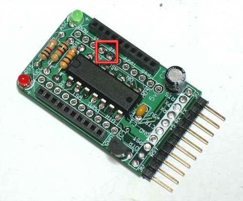
Now solder in a tiny jumper between the RTS pin and D3. This will tie the status of D3 to the status of the RTS pin which is can be configured to be used as the 'arduino reset pin'
Wire up the receiver
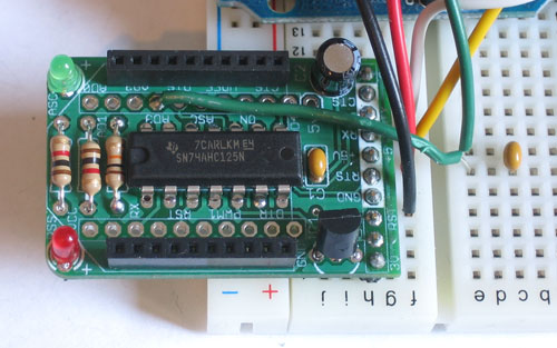
The transmitter XBee connects directly to the FTDI cable/computer and the receiver is wired to the target Arduino. Here I use a half-sized breadboard and rubber band since not much space is necessary. Solder a wire from pin D3 on the receiver XBee adapter, so that you can plug it into the breadboard. This is the mirrored reset line from the transmitter Xbee.

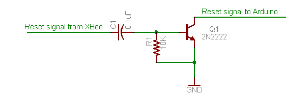
Xbee's are pretty weak and dont have the oomph to reset an Arduino on their own, so we need to wire it up to a transistor which will do the heavy lifting of pulling the reset line down. Pretty much any small NPN transistor will work just fine here. Put a 0.01uF to 0.1uF capacitor in series with the wire from the XBee, and connect the other side to the NPN transistor base. The emitter of the transistor connects to ground. Put a resistor around 10K between the base and emitter. This will pull down the base to keep the Arduino from resetting accidentally.
The collector goes to the Arduino's reset line.
Configure the receiver
Set up the receive XBee so that it will listen to changes on pin D3. Connect it to the FTDI cable and read in the current configuration just like the transmitter.
- The PAN ID should match the transmitter's.
- Set the baud rate to 19200 or 57600 to match the transmitter.
- Set the Packetization Timeout. This is what determines how long to wait before sending the characters over. We're doing some 'bulk transfer' when sending 10K programs over, so you'll probably want this number high like 10
- Set pin D3 to be a digital output, default high.
- Set the I/O Output to Disabled. This will prevent the receiver from displaying the status update in the serial line and instead just toggle the matching pin.
- Finally, set I/O line passing input address to FFFF. If you set up unique addresses for the receiver and transmitter xbees, of course you should change this to match but FFFF will match all addresses.
Now write the changes to the receiver XBee.

