tg_tower_timer_sept_2011
Table of Contents
TG Tower Timer
Developed on a Sparkfun 328 based Arduino. Initially interfaced via one wire to a Hobby Boards Relay but changed to individual port bits to relay control. 6 port bits are devoted to an LCD.
Relay Wiring
| Shelf 101 | Relay 1 | RJ45-1 | 6 |
| Shelf 102 | Relay 2 | RJ45-6 | 10 |
| Shelf 103 | Relay 3 | RJ45-4 | 8 |
| Shelf 104 | Relay 4 | RJ45-3 | 7 |
| Shelf 201 | Relay 5 | RJ45-5 | A0 |
| Shelf 202 | Relay 6 | RJ45-7 | A1 |
| Shelf 203 | Relay 7 | RJ45-2 | A2 |
| Shelf 204 | Relay 8 | RJ45-8 | A3 |
LCD Wiring
| Enable | 11 |
| RS | 12 |
| d4 | 5 |
| d5 | 4 |
| d6 | 3 |
| d7 | 2 |
| RW | GND |
RTC Wiring
| SDA | PC4/ADC4 | Ain4 |
| SCL | PC5/ADC5 | Ain5 |
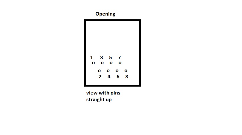
RJ45 connector glued on dead bug style
tg_tower_timer_sept_2011.txt · Last modified: 2011/10/19 13:43 by tomgee

